Posts

Showing posts from April, 2017

Definition of Ideal Transformer

Image
Definition of Ideal Transforme r An  ideal transformer  is an imaginary transformer which does not have any loss in it, means no core losses, copper losses and any other  losses in transformer . Efficiency of this transformer is considered as 100%. Ideal Transformer Model Ideal transformer model   is developed by considering a transformer which does not have any loss. That means the windings of the transformer are purely inductive and the core of transformer is loss free. There is zero  leakage reactance of transformer . As we said, whenever we place a low reluctance core inside the windings, maximum amount of flux passes through this core, but still there is some flux which does not pass through the core but passes through the insulation used in the transformer. This flux does not take part in the transformation action of the transformer. This flux is called leakage flux of transformer . In an ideal transformer , this  "Leakage Flux in T...

What is transformer ? Definition & Working Principle of Transformer

Image
Definition of Transformer  Electrical   power transformer   is a static device which transforms electrical energy from one circuit to another without any direct electrical connection and with the help of mutual induction   between two windings. It transforms power from one circuit to another without changing its frequency but may be in different   voltage   level.   This is a very short and simple definition of transformer , as we will go through this porrical power transformer , we will understand more clearly and deeply " what is transformer ? " and basic  theory of transformer . Working Principle of Transformer The  working principle of transformer  is very simple. It depends upon  Faraday's law of electromagnetic induction . Actually, mutual induction  between two or more winding is responsible for transformation action in an electrical transformer. Faraday's Laws of Electromagnetic Induction According t...

Electrical Power Transformer | Definition and Types of Transformer

Image
Definition of Transformer (adsbygoogle = window.adsbygoogle || []).push({}); A transformer is a static machine used for transforming power from one circuit to another without changing frequency. This is a very basic  definition of transformer . History of Transformer The  history of transformer  was commenced in the year 1880. In the year 1950, 400KV electrical power transformer  was introduced in high  voltage   electrical power  system. In the early 1970s, unit rating as large as 1100MVA was produced and 800KV and even higher KV class transformers were manufactured in year of 1980. Use of Power Transformer Generation of electrical power  in low  voltage level is very much cost effective. Hence electrical power  is generated in low  voltage level. Theoretically, this low  voltage  level power can be transmitted to the receiving end. But if the  voltage  level of a power is increased, the  ...

What are "series" and "parallel" circuits?

Image
What are "series" and "parallel" circuits? Circuits consisting of just one battery and one load resistance are very simple to analyze, but they are not often found in practical applications. Usually, we find circuits where more than two components are connected together. There are two basic ways in which to connect more than two circuit components:  series  and parallel . First, an example of a series circuit: Here, we have three resistors (labeled R 1 , R 2 , and R 3 ), connected in a long chain from one terminal of the battery to the other. (It should be noted that the subscript labeling -- those little numbers to the lower-right of the letter "R" -- are unrelated to the resistor values in ohms. They serve only to identify one resistor from another.) The defining characteristic of a series circuit is that there is only one path for electrons to flow. In this circuit the electrons flow in a counter-clockwise direction, from point 4 to po...

What is Ohm's Law

Image
Ohm's Law  A common phrase heard in reference to electrical safety goes something like this: " It's not voltage that kills, it's current! " While there is an element of truth to this, there's more to understand about shock hazard than this simple adage. If voltage presented no danger, no one would ever print and display signs saying:  DANGER -- HIGH VOLTAGE! The principle that "current kills" is essentially correct. It is electric current that burns tissue, freezes muscles, and fibrillates hearts. However, electric current doesn't just occur on its own: there must be voltage available to motivate electrons to flow through a victim. A person's body also presents resistance to current, which must be taken into account. Taking Ohm's Law for voltage, current, and resistance, and expressing it in terms of current for a given voltage  A common phrase heard in reference to electrical safety goes something like this: " It'...

What is Power in electric circuits

Image
Power in electric circuit  In addition to voltage and current, there is another measure of free electron activity in a circuit: power . First, we need to understand just what power is before we analyze it in any circuits. Power is a measure of how much work can be performed in a given amount of time.  Work  is generally defined in terms of the lifting of a weight against the pull of gravity. The heavier the weight and/or the higher it is lifted, the more work has been done.  Power  is a measure of how rapidly a standard amount of work is done. For American automobiles, engine power is rated in a unit called "horsepower," invented initially as a way for steam engine manufacturers to quantify the working ability of their machines in terms of the most common power source of their day: horses. One horsepower is defined in British units as 550 ft-lbs of work per second of time. The power of a car's engine won't indicate how tall of a hill it can climb or ...

What is Resister

Image
Because the relationship between voltage, current, and resistance in any circuit is so regular, we can reliably control any variable in a circuit simply by controlling the other two. Perhaps the easiest variable in any circuit to control is its resistance. This can be done by changing the material, size, and shape of its conductive components (remember how the thin metal filament of a lamp created more electrical resistance than a thick wire?). Special components called  resistors  are made for the express purpose of creating a precise quantity of resistance for insertion into a circuit. They are typically constructed of metal wire or carbon, and engineered to maintain a stable resistance value over a wide range of environmental conditions. Unlike lamps, they do not produce light, but they do produce heat as electric power is dissipated by them in a working circuit. Typically, though, the purpose of a resistor is not to produce usable heat, but simply to provide a precise ...

Voltage and current in a practical circuit

Image
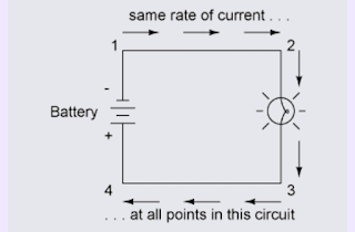
Voltage and current in a practical circuit Because it takes energy to force electrons to flow against the opposition of a resistance, there will be voltage manifested (or "dropped") between any points in a circuit with resistance between them. It is important to note that although the amount of current (the quantity of electrons moving past a given point every second) is uniform in a simple circuit, the amount of voltage (potential energy per unit charge) between different sets of points in a single circuit may vary considerably: Take this circuit as an example. If we label four points in this circuit with the numbers 1, 2, 3, and 4, we will find that the amount of current conducted through the wire between points 1 and 2 is exactly the same as the amount of current conducted through the lamp (between points 2 and 3). This same quantity of current passes through the wire between points 3 and 4, and through the battery (between points 1 and 4) (adsbygoogle = ...

What is resistance

Image
Resistance The circuit in the previous section is not a very practical one. In fact, it can be quite dangerous to build (directly connecting the poles of a voltage source together with a single piece of wire). The reason it is dangerous is because the magnitude of electric current may be very large in such a short circuit , and the release of energy very dramatic (usually in the form of heat). Usually, electric circuits are constructed in such a way as to make practical use of that released energy, in as safe a manner as possible. One practical and popular use of electric current is for the operation of electric lighting. The simplest form of electric lamp is a tiny metal "filament" inside of a clear glass bulb, which glows white-hot ("incandesces") with heat energy when sufficient electric current passes through it. Like the battery, it has two conductive connection points, one for electrons to enter and the other for electrons to exit. Connected to a sourc...